- Published on
Smart RGB lights [Part 1] - The hardware
- Authors

- Name
- Branimir Kirilov
Intro
I always felt like there isn't enough light on my desk. I don't have any dedicated lamps on it and I've always relied on the ceiling light, which is not ideal. So today, I had an idea - I could use some of the spare parts I've collected over the years from all my half-finished projects to create an RGB backlight for my desk that I can control from my mobile phone.
Hardware
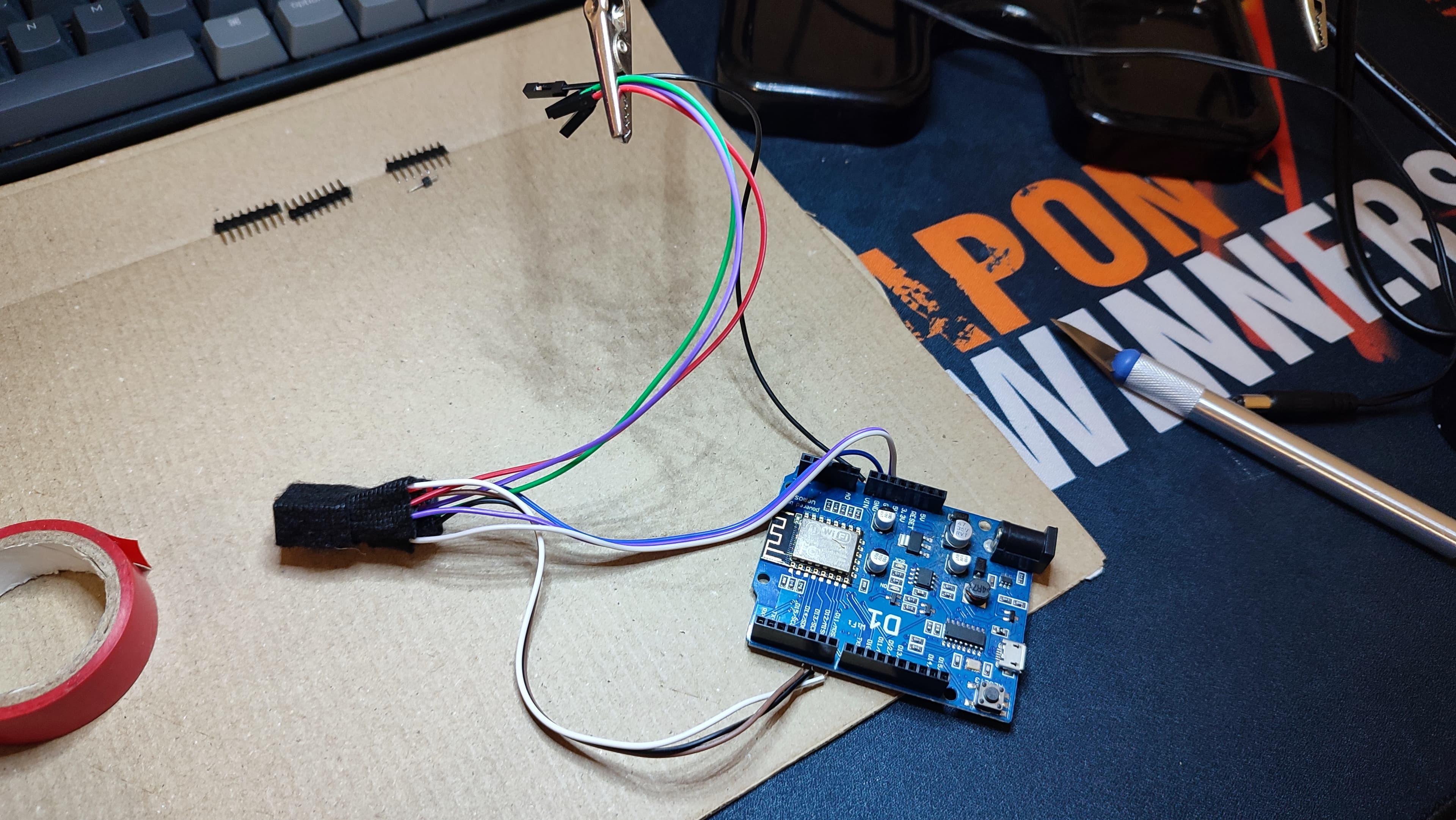
Excited about the idea of solving my desk lighting issue, I decided to rummage through one of the boxes of spare parts to see what I could find. I already knew that I have several WEMOS boards laying around and I decided to use the oldest one - D1, as it already has a dedicated power supply port. For those of you that don't know about this board - it is based on ESP8266 (it has WiFi capabilities) and it can be easily programmed with Arduino Studio. Additionally, there are a ton of helpful libraries developed by the community, which makes its usage easy.

Now that I answered the board question, I had to find an actual light source, after all the project would be pointless without it. After a bit of searching, I came across a dusty 12V LED strip and a few MOSFETs that were wrapped up with duct tape and in pretty rough shape. Despite their poor condition, I decided to salvage what I could and get to work.
At this point, I have everything except the power source. I used to have a DC charger with a voltage regulator but it seems like it has died a long time ago. The only thing that I have that could work is a 9v power supply from a network switch that is not in use anymore.
Since the LED strip is meant to run on 12v with this power supply I will not be able to get full brightness of it. On the other hand, this power supply has a jack that fits the barrel of the Wemose D1 board. I should be able to use it directly to power the board and the LED strip (from the VIN port) at the same time. However, this is conditional for my case, as the LED strip is not very long. The voltage regulator of the board should be able to dissipate the unused voltage without much trouble, although this is not the optional solution.
More info on powering Arduinos
Soldering
Connection scheme:
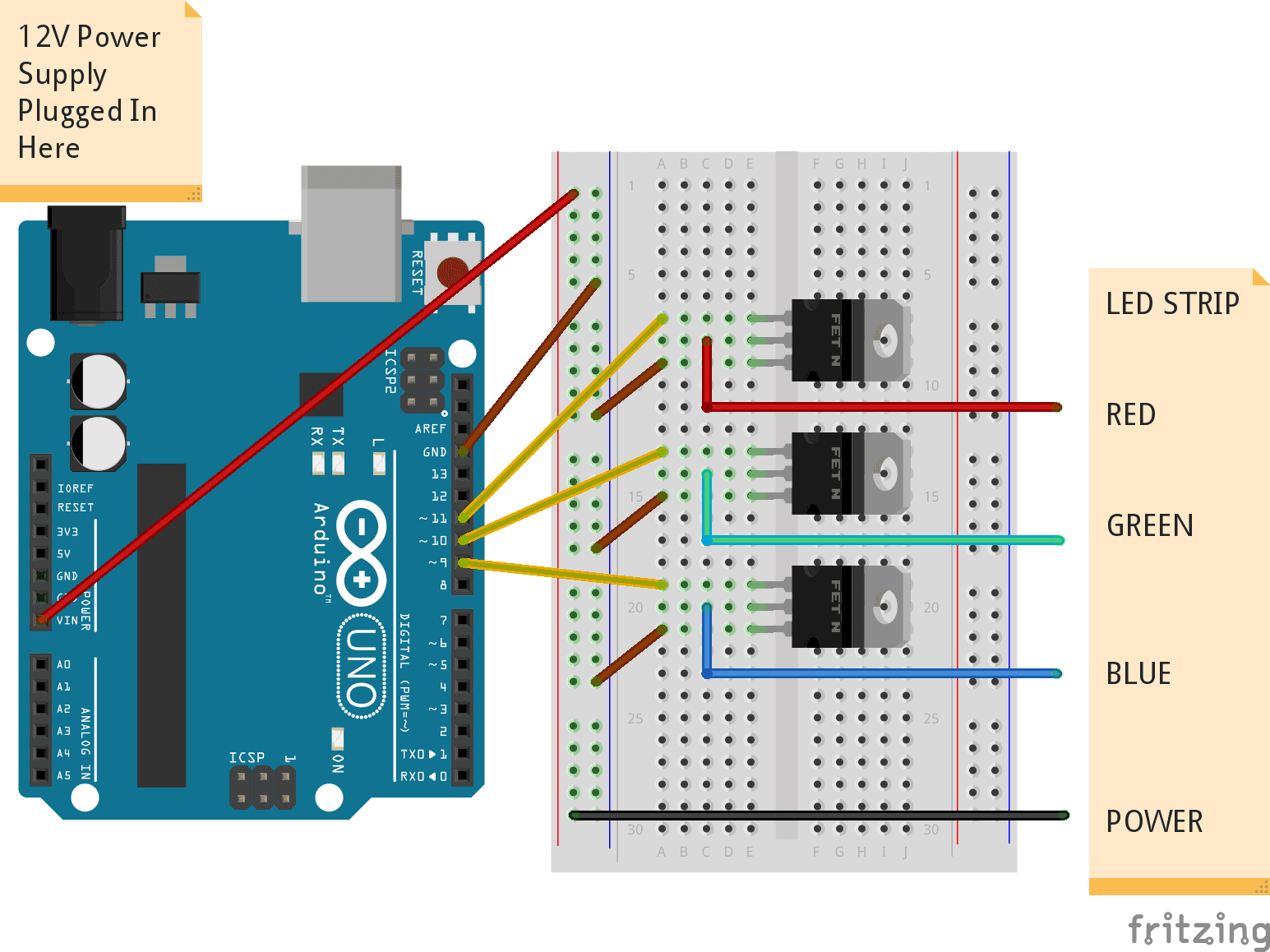
Luckily, I have a soldering station and a bunch of headers and cables that I could use. Of course, my soldering skills are limited, but at least this is a good chance to practice them.
The first step would be to clean up the LED strip and solder some headers to it for easier connection:

The next step is to solder the wires to the board and take care of the MOSFETs:
Writing the device code
I want this to be very simple, without overengineering it with any cloud-based solutions. It only needs to be accessible from my home, I don't need to turn on/off my desk lights from outside of my home.
For this reason, a simple HTTP server running on the board will be enough. At first, I'll only expose one endpoint that would expect the RGB values as query parameters and would set them to the LED strip. In the future, I may expose more endpoints that would start animations, timers, etc.
Configuring WiFi connection and network settings
We need to include
#include <ESP8266WiFi.h>Setup the network
IPAddress ip(192, 168, 1, 75);
IPAddress gateway(192, 168, 1, 1);
IPAddress subnet(255, 255, 255, 0);
- Then, in my setup function:
void setup() {
    WiFi.config(ip, gateway, subnet);
    WiFi.begin(ssid, password);
    while (WiFi.status() != WL_CONNECTED) {
      delay(500);
      Serial.print(".");
    }

    Serial.println("");
    Serial.println("WiFi connected");
    Serial.println("IP address: ");
    Serial.println(WiFi.localIP());
}
Testing the LED strip (and all the wiring)
- First step is to define the pins that we have connected. In my case:
#define REDPIN D7
#define GREENPIN D6
#define BLUEPIN D5
- Then, I'll just set the green pin to 255 in the setup() function, so I can test the connection:
pinMode(BLUEPIN, OUTPUT);
pinMode(GREENPIN, OUTPUT);
pinMode(REDPIN, OUTPUT);

analogWrite(REDPIN, 0);
analogWrite(BLUEPIN, 0);
analogWrite(GREENPIN, 255);
🎉 The LED is green!

Creating a web server
The next step is creating the HTTP server. Since there's already a library created for this, it's quite easy.
- First, we need to include:
#include <ESP8266WebServer.h>
- Then, the server should be created. I will create mine to run on port 93
ESP8266WebServer server(93);
- Then, in the setup function I will add the endpoint handlers and start the server. (I'll define the onHome method in the section below)
server.on(F("/"), onHome);
server.begin();
Serial.println("HTTP server started");
- In the loop function I need to tell the server to handle the client connections:
void loop() {
    server.handleClient();
}
- Now we need to act when clients go to "/" route:
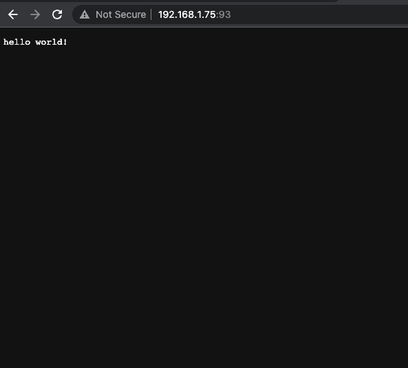
I'll simply return 200 and "hello world!" as text:
void onHome() {
    server.send(200, "text/plain", "hello world!");
}
- Now, let's upload to device and test
🎉 The server is working!
Creating endpoint to handle RGB color change
- We'll add a new endpoint called rgb:
server.on(F("/"), onRgb);
- Implement the onRgb handler:
void onRgb() {
    String r = server.arg("r");
    String g = server.arg("g");
    String b = server.arg("b");

    analogWrite(REDPIN, r.toInt());
    analogWrite(GREENPIN, g.toInt());
    analogWrite(BLUEPIN, b.toInt());

    server.send(200, "text/plain", "R: '" + r + "'" + "G: '" + g + "'" + "B: '" + b + "'");
}
- Let's also add some validation. The toInt() method will default to 0 if the conversion is not possible. However, we need to make sure colors are in the [0;255] interval:
int validColor(int color) {
    if (color < 0) {
        return 0;
    } else if (color > 255) {
        return 255;
    }

    return color;
}
We can then use the validator method as such:
void onRgb() {
    String r = server.arg("r");
    ...

    // toInt() defaults to 0 if no valid conversion is possible
    analogWrite(REDPIN, validColor(r.toInt()));...
}
- Time to test:
🎉 Endpoint is working and LED is in the correct color!

Full code can be found on GitHub
Attaching the LED to the desk and putting everything in a box
My girlfriend found a box from a bracelet she recently purchased and it was a solid fit. I might do something custom another day, but for now this will work:

I used some double sided tape to put the LED to the back of the desk:

Testing the lighting
After plugging in the power suply and dimming the main lights in the room, the result is quite good:


🎉 And with this the first part of the solution is ready! The next chapter will cover the implementation of web/native application with a color picker and some basic controls.